
Isuzu E-IDSS Diagnostic Service System [03.2021]
Legend
1.Exhaust camshaft assembly
2.Camshaft bearing cap4.Inlet camshaft assembly
3.Bolt
Removal
1. Rotate the crankshaft in the forward direction to align the first cylinder piston to the compression top dead center.
Check the TDC alignment position using a mirror, etc.

Legend
1.Crankshaft pulley
2.Mirror
3.TDC alignment position
2.Remove the cylinder head cover.
Refer to "Cylinder Head Cover"in this Section.
Install an M5 bolt to the sub gear.

. Remove the bafte plate(1).

5.Remove the camshaft bearing cap and camshaft.
Confirm that the camshaft bearing cap is marked.
The marking indicates the installation position.

Isuzu G-IDSS Diagnostic Service System [03.2022]
NOTE: Take necessary measures in advance so that the inlet side and exhaust side do not get mixed up.

Inspection
1. Inspect the camshaft.
Inspect the camshaft journal and cam for wear and damage. Replace if there are any problems.
NOTE: As the camshaft gear and sub gear cannot be disassembled, replace the entire camshaft assembly if there is abnormality found.
2. Inspect the clearance of the camshaft in the axis direction.
Insert a thickness gauge to measure the clearance between the camshaft gear andcamshaft bracket in the axis direction.
Replace the camshaft gear or camshaft if the measured value exceeds the limit.


3.Inspect the cam lobe for wear.
Measure the height of the cam lobe using a micrometer.
Replace the camshaft if the cam lobe height is under the limit.

4.Inspect the camshaft journal for wear.
Measure the diameter of the camshaft journal and uneven wear using a micrometer.
Replace the camshaft if the wear exceeds the limit.

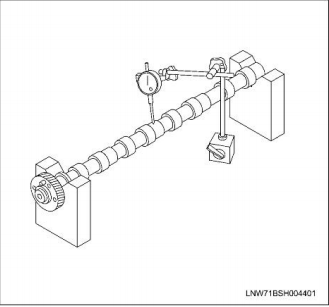
5.Inspect the camshaft for runout.
Place the camshaft in the V-block and use a dial gauge to measure any bending.
Slowly rotate the camshaft to measure deflection of the dial indicator.Replace the camshaft if the deflection exceeds the limit.

6.Measure the camshaft journal oil clearance.
a.Measure the inner diameter of the camshaft bearing using the cylinder gauge.
b.Read the difference of the inner diameter of the camshaft bearing and diameter of the camshaft journal.
Replace the camshaft bearing if the measured oil clearance exceeds the limit.

Installation
1. Rotate the crankshaft in the forward direction to align the first cylinder piston to the compression top dead center.
Check the TDC alignment position using a mirror, etc.

1.Crankshaft pulley
2.Mirror
3.TDC alignment position
2.Install the camshaft assembly.
Assemble the camshaft assembly so that the alignment marks on the camshaft gear end and the idle gear D are aligned.

Legend
1.Exhaust camshaft gear
2.Inlet camshaft gear
3.ldle gearD
3. Install the bearing cap.
Apply engine oil to the bearing upper.
Face the bearing cap front mark to the enginefront side, and assemble in order of numbers to the cylinder head.

4. Confirm that the camshaft bearing cap is aligned with the alignment position of the camshaft(1).

Apply engine oil to the threaded portion and tighten the bearing cap.
tighten up with the prescribed torque according to the order given on the figure.
Tightening torque:18 N-m(1.8kg-m/13 Ib-ft)
5.Remove the M5 bolt.

6. Adjust valve clearance.
7. Install the bafle plate(1).
Tightening torque:10 Nm(1.0 kg-m/87 lbin)

ISUZU US-IDSS Diagnostic Service Truck Diagnostic System [06.2021]
8.Install the cylinder head cover.
Refer to "Cylinder Head Cover"in this Section.


没有评论:
发表评论